
or any aftermarket radio that uses the Maestro HRN-HRR-CH1 radio harness.
Installation Video
Tools Needed:
- 9/32 inch socket (or 7mm socket)
- 3/8 inch socket (or 10mm socket)
- 18mm socket
- Ratchet wrench (Manual or powered)
- Socket extension
- Phillips head screwdriver
- Panel removal tool (Plastic preferred)
- Side cutter
- Zip Ties
- Flashlight or work light
- Wire fish or coat hanger
- Towel
- Lubricant
Step 1
Disassembly of your dash:
- Start by removing the lower dash panel located under and around the steering column. This panel is held in with pressure clips and can be removed with your hands by pulling back towards you on the top of the panel. The panel can than be lifted out of the way to reveal two screws. These can be removed with a 9/32 inch socket. Place screws in the cup holder for safekeeping.
- On top of the dash in the storage cubby under the rubber cover is another 9/32 inch screw to remove. Place screw in the cup holder for safe keeping.
- Use a panel removal tool to remove the window switch control from the center of the dash. The switch control can be gently pried out to reveal the main connector. Push back the red locking retainer and depress the tab to release the connector from the switch control.
- Removing the switch control from the previous step will reveal a fourth 9/32 inch screw. Remove the 9/32 inch screw. Place screw in the cup holder for safe keeping.
- Next up is the removal of the dash trim. Gently pull back towards yourself on the dash trim and it will come loose. You will need to lift this up and over the steering wheel, so it may be necessary to place the steering wheel in the lower position.
- Remove the four screws holding in the factory head unit. Place screws in the cup holder for safe keeping.
- At this point, you can remove your radio by pulling straight out.
- Remove the glovebox:
- Open the glove box
- Press in on the sides of the glovebox to release the pins, rotate down and remove completely
Step 2
Routing plug & play harness and RCA's to radio:
- Route the 2 four pin connections from the plug & play harness up from the glovebox to behind the radio.
- Repeat the same with the 6 Channel RCA's
- On one end you will see a tag that says "Connect To Source", this is the end that needs to be connected to the radio.
Step 3
Making connections to your aftermarket radio with Maestro harness:
- Connect the blue remote wire from the plug & play harness to the blue remote wire on the Maestro harness.
- We have included extra bullet connectors for you to use if your harness does not already come with a female bullet connector.
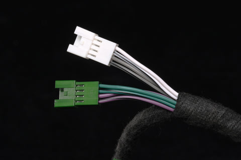
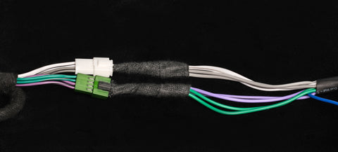
- Disconnect the green and white 4 pin connectors on the Maestro harness.
- Connect the male 4 pin connector from the plug & play harness with white and grey wires to the female Maestro harness connector with white and grey wires.
- Connect the male 4 pin connector from the plug & play harness with green and purple wires to the female Maestro harness connector with green and purple wires.

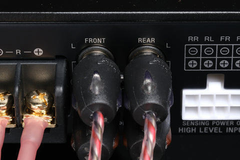
- Connect the RCA's to your radio:

- They are labeled F, R & S
- F (Front)
- Red to Red
- Clear to White
- R (Rear)
- Red to Red
- Clear to White
- S (Sub)
- Red to Red (Or Sub L)
- Clear to White (Or Sub R)
- If you radio only has one sub output, use the provided Y splitter. Connect the single male RCA into the Sub out from your radio and the two end with double female adapter into the Sub RCA from your 6 channel RCA bundle.
Step 4
Re-install your aftermarket radio:
- Confirm that all connections are made to the radio.
- You may choose to secure the RCA's with tape
- Re-install your aftermarket radio per your manufacturers specification.
Step 5
Remove the front passenger seat:
You do not need to fully remove the seat from the vehicle but you will want to at least lean it back into the back seat.
- Remove the two front seat bolts using an 18mm socket and ratchet wrench.
- Slide the seat forward and remove the two rear seat bolts using an 18mm socket and ratchet wrench.
- If you are going to fully remove the seat, lean the seat back and disconnect any connections under the seat.
Step 6
Remove the front door sill and kicker panel:
- Use a pry tool to remove the push pin that secure the door sill trim.
- Remove the second push pin towards the rear of the door sill.
- Pull out and up to release the door sill/kick panel.
Step 7
Routing the RCA's and plug & play harness to under the front passenger seat:
You may choose to run these wires a few different paths:
- Option #1
- Route the wires down behind the glovebox and keep them tight to the firewall.
- Route the wire behind the floor carpet and towards the bottom of the A pillar.
- Continue running the wire in the factory wiring channel along the door jamb until you reach the center of the seat.
- Route the wire under the carpet and come out in the opening in the carpet below the seat.
- Option #2
- Route them down behind the glove box and keep them tight to the transmission tunnel.
- Continue running the wires under the carpet and the plastic center console cover until you reach the center of the seat.
- Reach up under the carpet and pull them down towards the opening in the carpet under the front seat.
Step 8
Routing the power wire from the battery to the front seat area:
- Open and secure the hood to make access to the battery.
- On the passenger side firewall behind the battery, remove the two wire holders that secure the main harness by pulling off of the retaining pins.
- Pull back the corner of the firewall carpet to reveal the firewall grommet that we are going to run the power wire through.
- Use a small razor knife to cut through the butyl rubber covering the grommet.
- Insert your wire fish into the hole and insert it towards the floor.
- Attach the red power wire with the forked end to the end of the wire fish with tape.
- Work the wire fish into the vehicle until the power wire has passed through the firewall. Pull out the slack until the fuse block is near the battery.
- DO NOT CONNECT THE RED POWER WIRE TO THE BATTERY AT THIS TIME!
- Continue running the power wire through the factory wire channel near the door. Once you reach the middle of the seat area, run the power wire under the carpet and towards the opening in the carpet in the middle of the seat area.
- Use the provided zip ties to secure any loose wires.
Step 9
Routing the ground wire:
- Use the provided ground wire to connect to the factory ground location under the front passenger seat.
- Remove the factory ground nut using a 10mm socket.
- Place the ring terminal end of the ground wire in place and secure all wires with the factory 10mm nut.
Step 10
Making connections to the amplifier:
- Use four of provided industrial velcro pieces to attach to the bottom of the amplifier. Remove the film and adhere to the corners of the bottom of the amplifier.
- Remove the two screws from the amplifier cover plate using a phillips head screwdriver.

- Connect the black ground wire "GND"
- Connect the red power wire to "+12V"
- Connect the rear speaker wires:

- Green - Left Rear Positive
- Green/Black Stripe - Left Rear Negative
- Purple/Black Stripe - Right Rear Negative
- Purple - Right Rear Positive
- Connect the front speaker wires:

- White - Left Front Positive
- White/Black Stripe - Left Front Negative
- Grey/Black Stripe - Right Front Negative
- Grey - Right Front Positive
- Connect your RCA's:

- Isolate and tape off the Sub RCA's
- Connect Front RCA's (F)
- Red to Red
- Clear to White
- Connect Rear RCA's (R)
- Red to Red
- Clear to White
- Take this time to secure any loose wires and clean up and extra wire. We recommend placing any extra under the carpet.
Step 11
Connect the power wire to the vehicle battery:
- Mock up the fuse block and use the provided zip ties to secure it to the main harness near the firewall. Trim the excess zip tie off.
- Route the power wire the positive battery terminal.
- Remove the 10mm nut on the positive terminal, place the red power wire on the terminal and secure with the factory 10mm nut.
- Secure any loose wires as needed.
Step 12
Setting the gains on your Sony amplifier:
- Set the front filter to High Pass (HP) and move the dial so that the line is to 80.
- Set the rear filter to High Pass (HP) and move the dial so that the line is to 80.
- Find a song that will play for at least a few minutes.
- Confirm that your balance and fade is correct.
- Turn up the volume on your head unit to about 75% of the MAX volume.
- Using a small flathead screwdriver adjust the Front gain (Front Speakers) until your desired sound level is reached.
- Repeat the same for the Rear gain (Rear Speakers) setting.
- Once you are happy with your amplifier setting, replace the cover and secure the two screws.